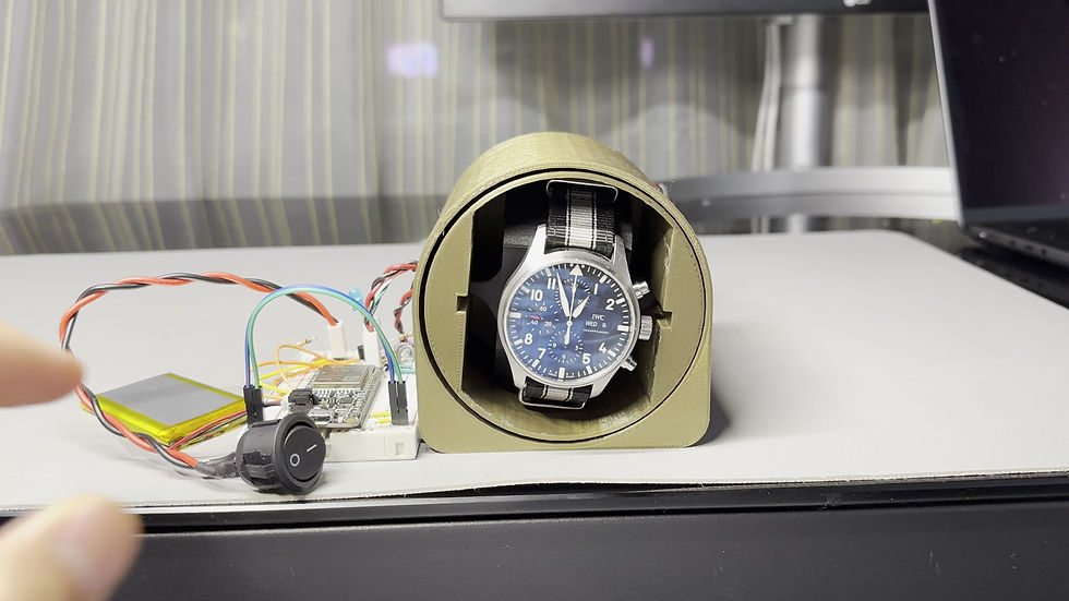
I engaged in the process of designing a watch winder from the ground up to keep mechanical watches running when they are not being worn. This included conceptualization, research and development, prototyping and testing. The final design is still in progress.
Background
Mechanical (Automatic) watches have a self-winding mechanism that winds the mainspring of the watch using the natural motions of the wearer's wrist. When an automatic watch is not worn, the mainspring unwinds and the watch stops running, therefore looses track of time (which is unhealthy for its mechanism). A watch winder simulates the natural motions of the wearer's wrist and keeps the watch wound and running.


Rotor (Semi-Circular Weight)
Concept Sketches


The Prototype (Proof of Concept)

This product is engineered for 3D printing, it has a modular design with only 4 distinct parts which were optimized to minimize the need for support during the printing process. The cost of the design is significantly lower compared to the market alternatives, while offering a unique feature. An IR optical sensor (interrupt sensor) is integrated in the design to enable precise homing and counting of revolutions. This feature represents a significant improvement over the existing solutions in the market, which typically rely on the estimation of revolutions through the measurement of the motor RPM. The microcontroller employed in the design is an Adafruit ESP32, which offers a vast array of capabilities, including the potential for future expansion such as a smartphone application for inputting custom direction and revolutions per day settings.
A blue LED was implemented to provide a visual indication of interruption detected by the IR sensor.
The watch winder will be programmed with a user-input feature that requests the specific revolutions per day required (it varies depending on the watch), with a default value of 800 revolutions per day. An additional input feature will enable the user to specify the desired rotation direction, with options for clockwise, counter-clockwise or alternate rotation. "Upon activation of the switch, the motor will activate for a period of approximately 5 minutes per hour. The number of revolutions executed during this active period will be calculated by dividing the total number of daily revolutions (as specified by user input) by the number of hours in a day (24) , resulting in approximately 33 revolutions per hour. Following the active period, the system will enter into a low-power sleep mode for a duration of 55 minutes, after which the cycle will repeat. This mechanism ensures the maintenance of the desired number of daily revolutions while minimizing power consumption."
In addition, the product is engineered to be stored in a safe, thus it is equipped with a Li-Ion battery for autonomous operation and a micro-USB port for battery charging when connected to an external power source. The programmatic logic is designed to automatically switch power to the battery when the external power source is disconnected."
Creative Design


The development of this project is ongoing. At present, efforts are focused on the design and implementation of a compact Printed Circuit Board (PCB) to minimize the size of electrical components and to get rid of the bulky breadboard. Concurrently, the enclosure design is being optimized to accommodate all the components within the space behind the bevel gear. Additionally, software optimization techniques are being employed to reduce power consumption through the utilization of sleep modes.

