Mechanical Engineering Design Co-op
Kuva Systems is an emerging environmental services company, developing a cost-effective camera solution for identifying and quantifying the location and flow rate of methane releases. The system employs advanced imaging technology and sophisticated algorithm to perform minute-by-minute measurements and provide accurate and reliable data for monitoring and mitigating methane emissions. The low-cost nature of the camera technology makes it accessible and easy to use for a wide range of industrial applications.
Working as part of a dynamic and agile team at Kuva Systems, I had the opportunity to participate in a wide range of projects, leveraging my skills and experience to drive meaningful contributions to the company. A notable accomplishment was identifying and resolving a leakage issue while simultaneously improving assembly efficiency, resulting in reduced costs. I was responsible for the conceptualization and design of a mechanism, the creation of specialized assembly fixtures, and the initiation of a shift towards injection molding. I was also responsible for designing the first batch of parts and negotiating with manufacturers, which resulted in cost savings of more than 80% for those components. These efforts resulted in overall improved workflow and increased cost-effectiveness of the company.

I can only share some details regarding my work, as I have signed a nondisclosure agreement and can only share what has been approved. All work is property of Kuva Systems.
Flapping Mirror Mechanism Redesign
Early Designs

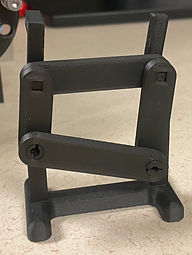


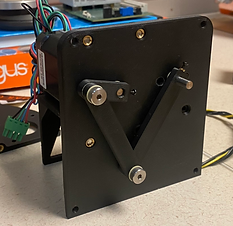
The iteration of Kuva’s gas monitoring system aims to compact the device and improve manufacturability, reduce cost, and minimize transportation size. The last critical development required to accomplish this is to relocate the motor and encoder which power and monitor position of the flapping mirror subassembly. Completing this process opens the opportunity to improve the existing design by increasing the imaging rate and quality.
To determine the optimal design for the project, an extensive series of tests were conducted to evaluate various design factors and their impact on the performance of the flapper mirror mechanism. The primary objective of these tests was to identify a design that could withstand a minimum of 40,000 hours of operation at a frequency of at least 10Hz, under a range of varying weather conditions.
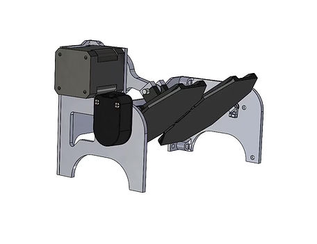
Through the testing process, it was determined that a four-bar linkage mechanism was the most effective in meeting these requirements while also ensuring minimal costs. Once this optimal design was identified, additional design optimization was conducted to enhance the manufacturability and efficacy of the system, ultimately resulting in the implementation of a crank rocker mechanism
Benefits of the four bar linkage mechanism
-
Uni-directional rotation of the motor requires less current than flapping it. Lower current will allow us to drive the mechanism at a higher frequency and will free up current to be used by other components in the system.
-
We can optimize the input motor rotation pattern to output a linear output flapping pattern which allows for easier image generation by the software.
-
Additionally, we can improve duty cycle of the flapping mirror by changing linkage lengths to increase sampling (motor time spent scanning in a direction) while maintaining the same frequency. This would be best suited for unidirectional scanning.
-
We can utilize the mechanism as a means of transmission. This would allow us to move the motor position so that it is no longer protruding without the need for an additional belt drive to transmit power.

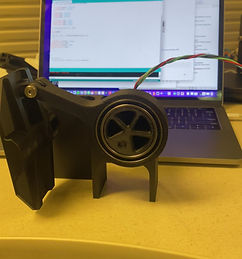
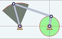
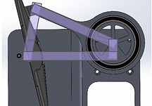
The original design for driving the mirror utilized a direct-drive reciprocating motion, where the motor was mounted directly onto the mirror carrier shaft, providing a continuously alternating acceleration and reversal of the motor. In re-evaluating the motor positioning within the device's chassis, two alternative mechanisms were identified that could effectively transmit power to the mirror shaft while relocating the motor: the crank rocker mechanism and a belt drive.
The belt drive uses a timing belt to transfer power to the mirror, causing it to oscillate. This mechanism is able to maintain the same motor acceleration profile as the original direct-drive reciprocation mechanism, thereby preserving similar power requirements and imaging capabilities.
Crank Rocker
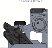

Belt Drive

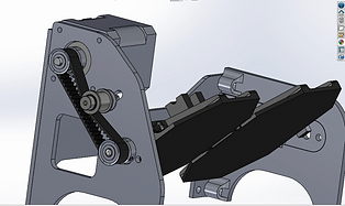
The crank rocker mechanism is a specific configuration of a 4 bar linkage where in one of the arms completes full rotations and the output arm simply rocks back and forth. The mechanism is well known for converting rotational motion into oscillating rotary motion. Additionally, by adjusting the lengths of the members in the mechanism, different velocity profiles can be achieved which improve linearity of the scan or change the duty cycle. Changing the duty cycle may be useful for optimizing unidirectional or bidirectional scanning as it provides more “time per pixel” while maintaining the same frequency.
The crank-rocker and timing belt mechanisms will be analyzed for the frequency that they are able to achieve, the power that they require, and the robustness of their design.
Testing the prototype

Accelerating the stepper motor to 10HZ

Plotting the encoder data and comparing it with the calculated theoretical
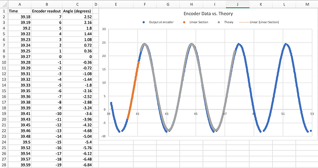
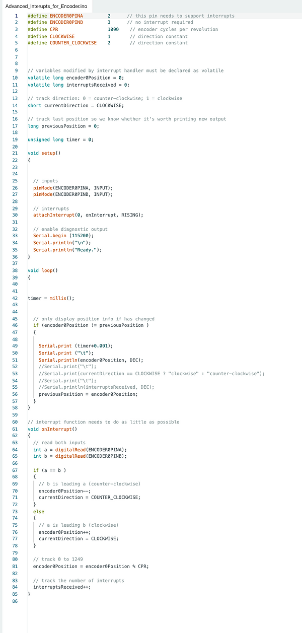
Reading the encoder data (using interrupts)
"Following the successful completion of prototype testing and validation of data, the project was transferred to my colleagues for further development as my co-op term had come to a conclusion. The prototype demonstrated promising results and the data gathered during testing validated the feasibility of the design concept, providing a solid foundation for future progress."
O-ring Seal Design
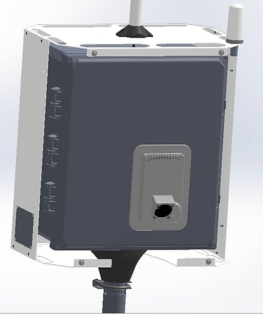
"My initial project at Kuva Systems was focused on resolving a leakage issue in the heat exchanger assembly. To identify the root cause of the problem, I conducted a thorough root cause analysis of the assembly. The analysis revealed that the thickness of the rear doors in inventory (3mm) was inconsistent with the thickness of the CAD model (4mm), resulting in a 25% variation which compromised the seal.
As I had limited prior knowledge in the field of O-rings and seals, I conducted extensive research and study of various seal designs. Based on my findings, I proposed a new design that eliminated the dependency of the O-ring compression on door thickness. Additionally, I recommended changing the material of the O-ring from neoprene to nitrile rubber, which provided improved durability and resistance to environmental factors. I also designed a static non-circular groove, with 30% vertical compression, 90% volumetric fill and 5% stretch on the O-ring, to optimize the seal performance. These changes effectively solved the leakage issue, resulting in improved assembly performance and reliability."

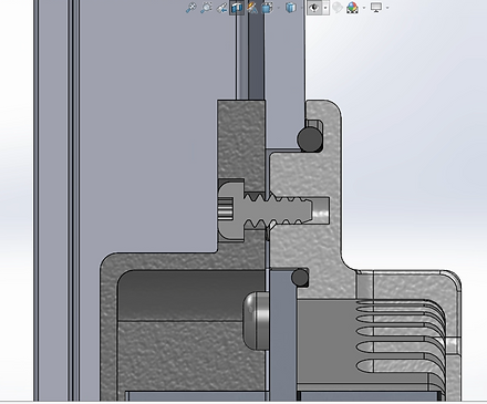
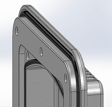
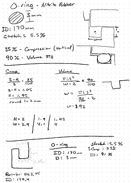
The change of O-ring material to nitrile rubber provided additional benefits beyond improved seal performance, including reduced assembly complexity and labor costs. The neoprene O-ring, which was previously used, came in rolls of 100ft, requiring manual cutting and assembly. Through close collaboration with the technicians, it became clear that this assembly process was tedious and prone to human error.
To further optimize the assembly process, I consulted with my manager and was provided with the guidance that "All assemblies should be designed to be properly assembled by a 15-year-old, since 80% of manufacturing incidents are due to human error." This guidance prompted me to investigate alternative O-ring options that eliminate the need for manual cutting, ultimately resulting in the selection of a conventional O-ring that could be easily assembled with minimal human intervention, reducing the potential for assembly errors and increasing overall efficiency of the manufacturing process.
The proposed design was rigorously tested to ensure compliance with industry standards, in particular, the IP65 rating for dust and water ingress protection. The testing methodology involved simulating various environmental conditions, including exposure to dust and water, to verify the integrity of the seal and the functionality of the camera system. As a result of these tests, it was confirmed that the design met or exceeded the IP65 rating standard, validating its suitability for use in harsh environmental conditions.
Injection Mold Design

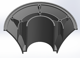
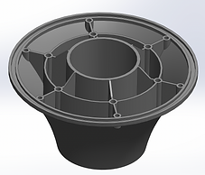
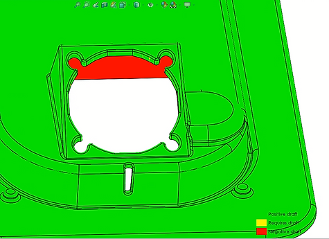
After successfully resolving the leakage issue with the heat exchanger cover, my next task was to optimize the design for the manufacturing process. One of the key considerations was to make the design suitable for injection molding. This involved making sure that the walls of the piece were maintained at a consistent thickness of 2mm throughout, and the inclusion of a draft angle in the direction of the mold pull. Additionally, to aid in the molding process and improve the final product quality, ribs and cavities were strategically placed to maintain the wall thickness and prevent the formation of sink marks, particularly around the O-ring's groove. These design changes helped to streamline the manufacturing process, improve the product's final quality and reduce the costs.
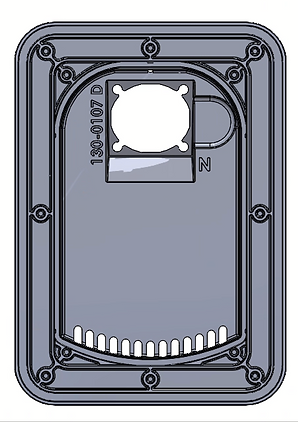
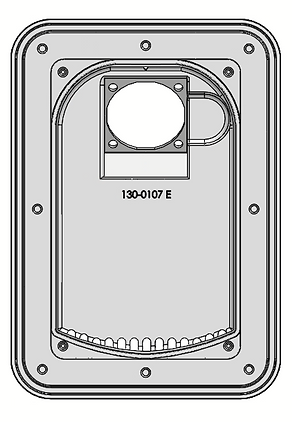
In order to minimize tooling costs, the design of the external fan mounting holes was modified to eliminate the need for the use of inserts or sliders. To achieve this, the direction of the holes was oriented perpendicular to the part and made oval-shaped, allowing the screw to be inserted diagonally. This design modification ensured full constraint of the fan and was validated via animation simulations.

Draft Analysis

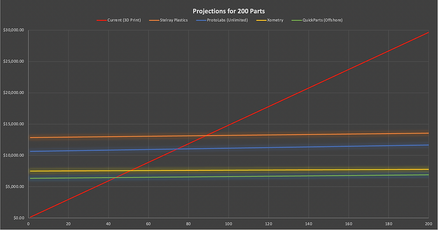
The graph provided illustrates a comparison of costs between injection mold manufacturers and the current 3D printing method. The cost for injection mold tooling ranges between $6,000 and $13,000 USD, however, it is cost-effective in the long run with price per part ranging from 2 to 4$. In contrast, the cost per 3D printed part is significantly higher at $150. Furthermore, the return on investment can be observed to be less than 100 parts, which indicates that using injection molding would be a more cost-effective option in this scenario.
More Design Work

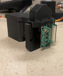
Universal RGB Camera Mount

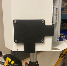


Nameplate Drill Holes Fixture
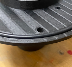
Pan Hub and Seal Design
